Chapter 3: Material Flow (II) – Point- and Length-Oriented Objects in Production and Assembly
Modeling material flow – Point-oriented and length-oriented objects
MUs are processed, transported and stored by material flow objects. Generally, we can differentiate between two categories of material flow objects: point-oriented and length-oriented material flow objects.
Point-oriented material flow objects do not take into account the physical length or dimension. MUs are processed or stored in these objects on a fixed location for a given time. Material flow objects that belong in this category are:
- SingleProc
 is a single station that can process one MU at a time. It receives an MU from its predecessor object and releases the MU after the defined set-up and processing times to its successor object.
 - ParallelProc
 is a station that can process several MUs at a time. ParallelProc corresponds to two or more SingleProc stations that receive the same parts from the same predecessor.
 - AssemblyStation
 assembles MUs received from multiple predecessor objects together. You can create an Assembly Table to define the number of parts required from each predecessor to create the final product.
 - DismantleStation
 removes assembled parts from the main MUs.
 - Buffer
 can temporarily hold MUs from the predecessor object when the successor object is unavailable to receive them. Buffer dimensioning is one of the main use cases for simulation study, as a sufficient buffer dimension is required to prevent production stop. A buffer can either be a queue (FIFO – First In First Out) or a stack (LIFO – Last In First Out).
 - FlowControl
 is used to model different strategies for distributing and merging the flow of materials from one or multiple predecessor objects to one or multiple successor objects.
On the other hand, length-oriented material flow objects take into account their length and dimension as well as the length and dimension of the MUs that pass through them. Length-oriented material flow objects use the length, dimension, and speed information to determine the time required to pass on the MUs to the successor. Material flow objects that belong in this category are:
- Line
 is used to model a conveyor system that transports MUs along its entire length with a constant speed. An MU that is currently transported along the Line cannot pass another MU in front of it.
 - Angular converter
 connects two Line objects and changes the conveying direction of the MUs accordingly. It can only move one MU at a time.
 - Turnplate
 is used to model a rotating platform. It can connect two or more Line objects and ensure the uniform orientation of the MUs leaving it by rotating them.
Exercise: Point-oriented objects
In this exercise, we will extend the previous simulation and model the manufacturing area using point-oriented material flow objects. It is highly recommended that you only change the Manufacturing frame in the folder FacilityArea in the Class Library.
Step-by-Step:
- In the frame .Models.FacilityArea.Manufacturing, insert the material flow objects and rename them as shown in the figure below. Hold down the Ctrl-key to insert the same object several times without returning to the Toolbox each time.
- Connect the objects using Connector. Hold down the Ctrl-key and left-click on the objects to insert the Connector several times and create multiple connections without returning to the Toolbox each time.
Tips: To create a non-straight connection, click on the first object you want to connect, set one or more anchor points by clicking on the free area in the frame, and finally click on the second object you want to connect. This is especially useful if the connectors would overlap each other. You can select and move the anchor points afterward.

Figure 16: Objects in the Manufacturing frame
- Double-click on each object to open the dialog properties. Rename the objects as shown in the figure and modify the attributes according to the following parameters:
- Buffer (all) → Capacity: 8, Buffer type: Queue
- Punching → Processing time: 3:00
- Bending → Processing time: 3:00
- LaserCutting → Processing time: 1:00
- Coating → X-dimension: 2, Y-dimension: 2, Processing time: 6:00
- Washing → X-dimension: 1, Y-dimension: 2, Processing time: 2:00
- The default exit strategy of the FlowControl is cyclic, which means that the MUs will be passed on cyclically to all successors. However, the QualityGate should only pass on the good parts and reject the bad parts, e.g. randomly based on a distribution function.
- Double-click the QualityGate and select “Percentage” from the dropdown menu. Click on Apply. The button Open List should appear. Click on this button and change the distribution percentage according to the figure below. Make sure that the successor 1 is the Exit interface and successor 2 is the Reject drain. Click on Apply and OK
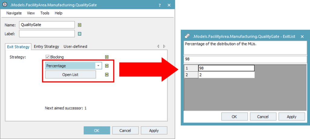
Figure 17: Exit strategy of the FlowControl
Download:
The final state of the simulation model up to this exercise can be downloaded here Tutorial_Model_02.
Exercise: Length-oriented objects
In this exercise, we will extend the previous simulation and model the assembly area using point-oriented and length-oriented material flow objects. Similar to the previous exercise, it is highly recommended that you only change the Assembly frame in the folder FacilityArea in the Class Library.
Step-by-Step:
- In the .Models.FacilityArea.Assembly frame, insert the material flow objects and rename them as shown in the figure below. Except for the Pallet_Source, all Source objects produce the standard Entities. The MUs for the Pallet_Source should be of the class Container MUs.
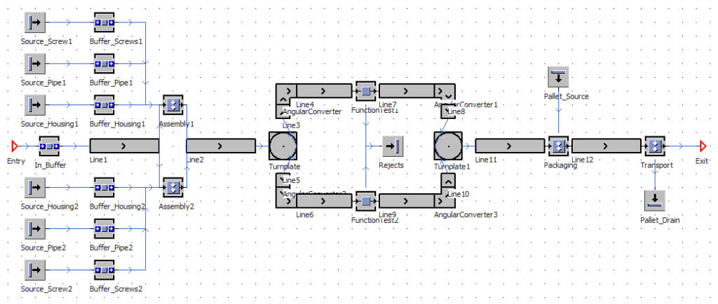
Figure 18: Assembly frame
- There are two ways to insert the length-oriented objects (Line, AngularConverter, Turnplate) into the model:
- Left-click on the object in the Toolbox. Left-click on the designated location in the frame to insert the starting point. The cursor will change into drawing mode and show the angle and length while you move the mouse. Left-click again on the frame to insert the next arc point. Press the Esc-key to the drawing mode.
- Drag and drop the object from the Toolbox into the frame. It will be inserted with its default properties. You can edit the properties afterward using the dialog property window.
- Double-click on the Line1 to open its dialog property window. In the Attributes tab, change the Length to “5” and uncheck the box of the attribute “Accumulating”. This means that all succeeding MUs will stop moving when other MUs in front of them cannot exit the Line. Repeat this step for Line2.
- For length-oriented objects that consist of multiple segments, you need to define the properties for each segment, i.e. its length and position. To edit the properties, navigate to the Curve tab and click on the Segments A new window will show the Tangential angle [°] and the Length [m] for each segment.
- To add a new segment, press the Enter-key on the last row to create a new row. Enter the tangential angle and the length of the new segment and click Apply/OK. The figure below shows the properties of the AngularConverter.
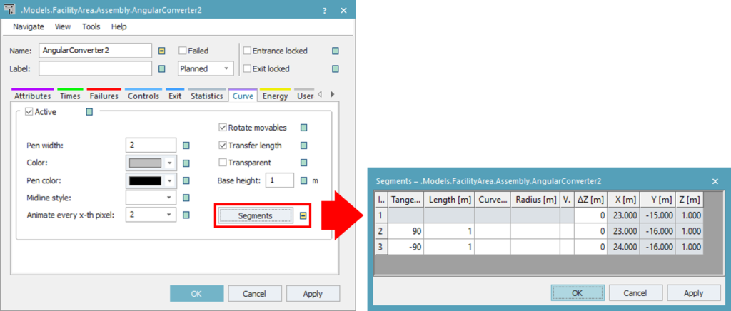
Figure 19: Edit segment in length-oriented objects
- Connect the objects using Connector:
- For each Assembly station, the order of the connectors from its predecessors should be (1) predecessor Line, (2) Buffer_Housing, (3) Buffer_Pipe, (4) Buffer_Screws
- For each FunctionTest station, the order of the connectors to its successors should be (1) predecessor Line, (2) Rejects
- For the Packaging station, the order of the connectors from its predecessors should be (1) Pallet_Source, (2) predecessor Line.
- For the Transport station, the order of the connectors to its successors should be (1) Exit interface, (2) Pallet_Drain.
- Double-click on the Assembly Choose “Predecessors” from the dropdown menu of the Assembly table. Click on the Open button. Enter the predecessor connector number and the number of parts that the Assembly station should take from its predecessors. The Assembly station should take each one Housing, one Pipe, and four Screws from the corresponding Buffer.
- Select “New MU” from the dropdown menu of the Exiting MU Click on the button, choose Select Object, and select the Radiator entity. The MUs exiting the Assembly station will now be the final product.
- Navigate to the Times tab. Set the processing time to “3:30”.
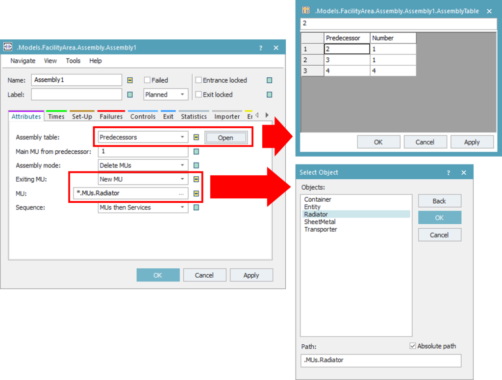
Figure 20: Dialog properties of the Assembly station
- Double-click on the FunctionTest Set the processing time to “3:30”. Navigate to the Exit tab and change the strategy to “Percentage”. Modify the list so that 98% of the parts go to the succeeding line and 2% of the parts are rejected.
- Double-click on the Packaging We want to load the finished products onto pallets. Therefore, the main MU should be the Container from the Pallet_Source and the Assembly mode should be set to “Attach MUs”. Each pallet can load two of the radiators. Change the Assembly table to predecessors and enter the required amount of the radiators. Finally, navigate to the Times tab and set the processing time to “2:30”.
- Double-click on the Transport This is a dismantle station, where the radiators are sent to shipment and separated from the pallets. Set the Dismantle mode to “Detach MUs” and enter the correct number of the successor. The radiators should be passed on to the Exit interface, while the containers are sent to the Pallet_Drain. Finally, navigate to the Times tab and set the processing time to “1:00”.
Download:
The final state of the simulation model up to this exercise can be downloaded here Tutorial_Model_03.
Running the simulation model
The EventController ![]() runs the simulation model and manages the events during simulation run. By default, the root frame that is created automatically when you start a new model will include an EventController by default. You can start a simulation by double-clicking on the EventController object in the frame or in the Home ribbon tab and pressing the Start/Stop button.
runs the simulation model and manages the events during simulation run. By default, the root frame that is created automatically when you start a new model will include an EventController by default. You can start a simulation by double-clicking on the EventController object in the frame or in the Home ribbon tab and pressing the Start/Stop button.
During a simulation run, Plant Simulation will show the animation of the material flow. Material flow objects also show their current state using LED icons in different colors on top of their default icon:
- Red → Object is failed
- Blue → Object is paused
- Green → Object is working
- Yellow → Object is blocked
- Brown → Object is setup
- Cyan → Object is in recovery
- Orange → Object is waiting for resources
These animations can lead to a slower execution speed in a large model. Click on the icon MUs ![]() on the Home ribbon tab to switch on/off the animation of MUs during simulation run. Click on the icon Icons
on the Home ribbon tab to switch on/off the animation of MUs during simulation run. Click on the icon Icons ![]() on the Home ribbon tab to switch on/off the animation of LED icons.
on the Home ribbon tab to switch on/off the animation of LED icons.
Exercise: Simulation run & model presentation
In this exercise, you will set the Start and End time of the simulation and run the simulation that you created. Finally, you will modify the presentation of the frames so that you can see the complete facility on one frame.
Step-by-Step:
- Open the .Models.Plant Double-click the EventController object in the frame or click on the EventController icon on the Home ribbon tab.
- Navigate to the Settings Enter value on the field End so that the simulation runs exactly for one whole day. The time format is DDD:HH:MM:SS.XX. Check the box “Show summary report” to automatically create a summary report after the simulation run. Click on Apply.
- Navigate to the Control tab and press the Start/Stop button to start the simulation. Watch the simulation run and view the summary report afterward.
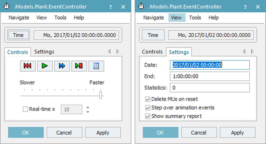
Figure 21: EventController
- If you double-click on the Manufacturing frame and the Assembly frame inside of the Plant frame, you can view the animation of the MUs. However, you can only see the animation for each frame separately this way and not the animation of the whole process.
- Open the Manufacturing frame. Click on the icon Representation
 from the General ribbon tab. Change the Representation mode to “Contents” and enter the value as shown in the figure below. Repeat the steps in the Assembly frame.
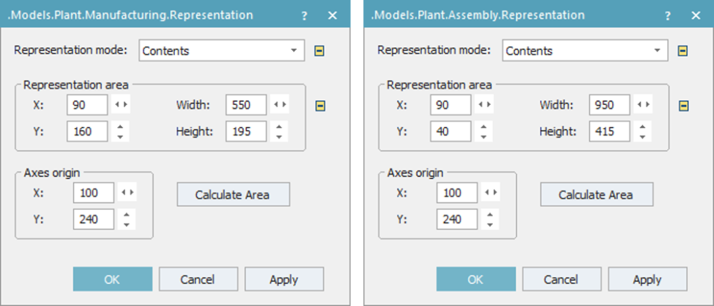
Figure 22: Dialog properties for representation of the Manufacturing frame (left) and Assembly frame (right)
- If you double-click on the Manufacturing frame and the Assembly frame inside of the Plant frame, you can view the animation of the MUs. However, you can only see the animation for each frame separately this way and not the animation of the whole process.
- Open the Manufacturing frame. Click on the icon Representation from the General ribbon tab. Change the Representation mode to “Contents” and enter the value as shown in the figure below. Repeat the steps in the Assembly frame.
Download:
The final state of the simulation model up to this exercise can be downloaded here Tutorial_Model_04. Your simulation model should look similar to the figure below
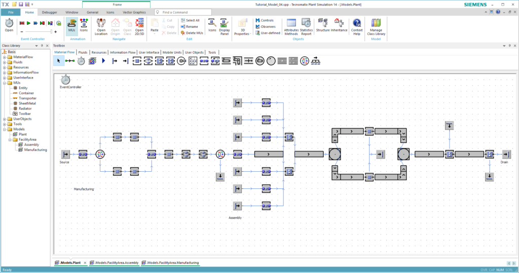
Figure 23: Final model of this chapter
