Chapter 4: Resources – Modeling Workers, Shifts and Service Logic in Plant Simulation
This chapter will introduce you to the modeling of resource objects in Plant Simulation. After completing this chapter, you will be able to:
- Understand resource objects in Plant Simulation
- Extend your model with workers and resource objects
Modeling workers and resources
In the previous chapter, you have created the processing stations of your production facility. Plant Simulation provides additional resource objects to integrate human factors and shift calendars to the processing stations.
Worker ![]() represents a person who works at a processing station, such as SingleProc, ParallelProc, Assembly, or DismantleStation. Workers can provide different types of services and have different parameters, such as efficiency and speed, to determine their behavior.
represents a person who works at a processing station, such as SingleProc, ParallelProc, Assembly, or DismantleStation. Workers can provide different types of services and have different parameters, such as efficiency and speed, to determine their behavior.
Worker can only work at a processing station if there is a Workplace ![]() attached to this station, which is not already occupied by another worker.
attached to this station, which is not already occupied by another worker.
WorkerPool ![]() introduces Worker to the simulation. It creates the number of Worker instances with given parameters according to the creation table. Every Worker starts from the WorkerPool. They return to the WorkerPool during shift breaks and at the end of the shift, and remain in there when they do not have any work assigned. The WorkerPool also determines how workers travel between the WorkerPool and the assigned station. Workers can either move freely within the area, walk along footpaths, or teleport directly to the workplace.
introduces Worker to the simulation. It creates the number of Worker instances with given parameters according to the creation table. Every Worker starts from the WorkerPool. They return to the WorkerPool during shift breaks and at the end of the shift, and remain in there when they do not have any work assigned. The WorkerPool also determines how workers travel between the WorkerPool and the assigned station. Workers can either move freely within the area, walk along footpaths, or teleport directly to the workplace.
FootPath ![]() connects the WorkerPool to workplaces. It is a length-oriented object, which means that the length of the footpath and the speed of the worker will be used to determine the required travel time during the simulation.
connects the WorkerPool to workplaces. It is a length-oriented object, which means that the length of the footpath and the speed of the worker will be used to determine the required travel time during the simulation.
Broker ![]() manages the service requests of all processing stations and the provided services of the workers. If the provided service of a worker matches the requested service of a processing station, the Broker assigns the worker to this station and triggers the event for the worker to leave his WorkerPool and go to the requested station.
manages the service requests of all processing stations and the provided services of the workers. If the provided service of a worker matches the requested service of a processing station, the Broker assigns the worker to this station and triggers the event for the worker to leave his WorkerPool and go to the requested station.
Shift calendar ![]() is used to model work shifts in your plant. You can define as many shifts as you need and set individual break times for each shift. You can also define exceptions for days on which no or reduced work is done in your plant, e.g. on a national holiday.
is used to model work shifts in your plant. You can define as many shifts as you need and set individual break times for each shift. You can also define exceptions for days on which no or reduced work is done in your plant, e.g. on a national holiday.
Exercise: Resource objects
In this exercise, we will extend the previous simulation with resource objects. We want to model two types of Worker. Each will provide a different type of service and work either in the manufacturing or in the assembly area. We also want the workers to work in two shifts according to a ShiftCalendar. Similar to previous exercises, it is highly recommended that you only make changes in the frames in the folder FacilityArea in the Class Library.
Step-by-Step:
- Expand the Resource folder in the Class Library. Right-click on the Worker class and select Derive from the context menu.
- Double-click on the derived Worker class and rename it to “WorkerManufacturing”. Deactivate the inheritance of the provided services. Click on the Services button and add a new service type “Manufacturing” as shown in the figure below.
- Repeat the previous steps to derive a new class “WorkerAssembly” from the Worker class. Change the attributes so that the WorkerAssembly class will provide a new service type “Assembly”.
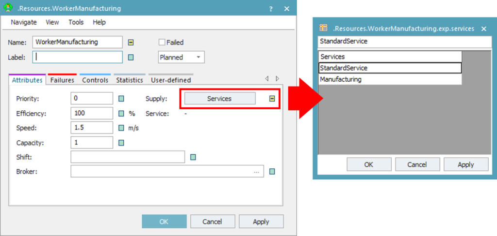
Figure 24: Services dialog properties of the WorkerManufacturing class
- Open the Manufacturing frame under the folder FacilityArea. Navigate to the Resource tab in the Toolbox. Drag & drop the Workplace object from the Toolbox onto the frame. We want each single processing station to have one workplace and each parallel processing station to have two workplaces.
Tips: If you place a Workplace near a processing station when you use drag & drop in the frame, it will be linked automatically to the processing station. Alternatively, you can also drag & drop the Workplace onto the processing station. Check the Attributes tab of the Workplace to make sure that the workplace is linked to the correct station.
- Insert a WorkerPool, ShiftCalendar, and Broker from the Toolbox into the frame.
- Draw FootPath to connect the WorkerPool to each Workplace. The beginning and the end of each footpath is connected by Connectors. This way, you can connect a footpath to several workplaces as well as to several other footpaths. The finished model in your Manufacturing frame should look similar to the figure below.
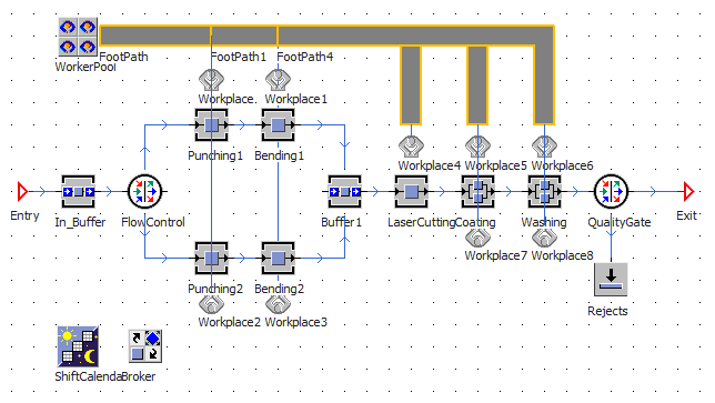
Figure 25: Extended model of the Manufacturing frame
- Drag & drop the ShiftCalendar and the Broker onto the WorkerPool instance in the frame to link them.
- Double-click on the WorkerPool. In the Attributes tab, the WorkerPool should automatically refer to the assigned Broker and ShiftCalendar.
- Deactivate the Workers inheritance and click on the button Creation Table. Drag & drop the WorkerManufacturing class from the Class Library onto the row below the Worker Set the values in the creation table as shown in the figure below. The WorkerPool will have 9 manufacturing workers for each shift with reduced efficiency in the second shift.
Tips: The ShiftCalendar creates two shifts by default. Make sure that the shift name in the WorkerPool matches exactly with the shift name defined in the ShiftCalendar. Double-click on the ShiftCalendar to see the defined shift times.
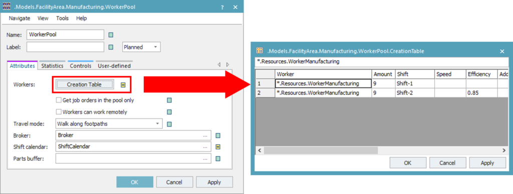
Figure 26: WorkerPool dialog properties
- Now you will need to link the processing stations to the Broker so that they are able to send service requests. Drag & drop the Broker instance onto each processing station in the frame.
- Double-click on a processing station, e.g. Punching1 Navigate to the Importer tab. You should see here that the correct Broker is assigned to this station.
- Set the Importer to be Active. Deactivate the service inheritance and click on the Services Set the required service to “Manufacturing” and enter the required amount, as shown in the figure below. Repeat this step for each processing station in the Manufacturing frame. Note that the required amount must match the number of workplaces linked to this station.
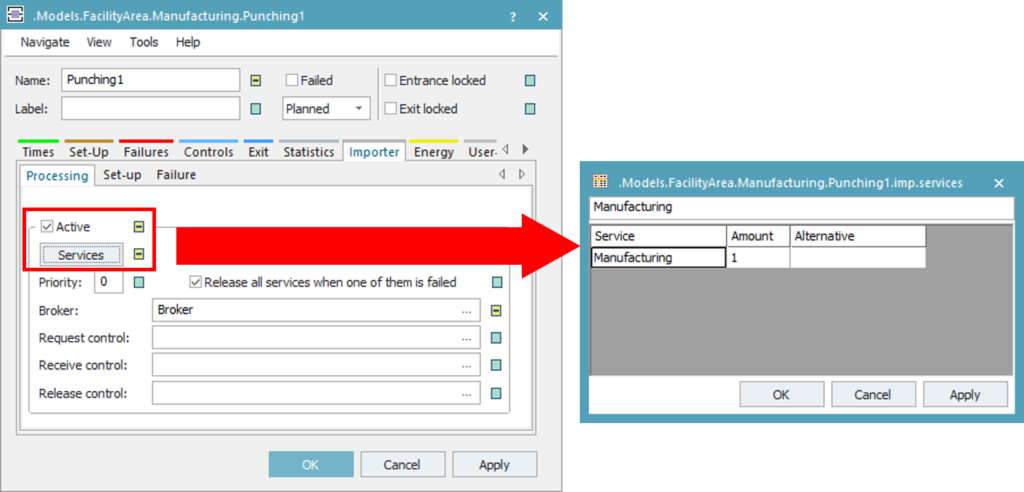
Figure 27: Importer for defining required services of a station
- Repeat all previous steps to create the WorkerPool, Broker, ShiftCalendar, and Workplaces in the Assembly The following parameters differ from the Manufacturing frame:
- The Packaging station should have two workplaces. The Transport station does not need any workplace. All other stations should have one workplace each.
- Use the WorkerAssembly class for the creation table in the WorkerPool. Set the number of workers to “6” for each shift.
- Set the travel mode to “Move freely within area”. You will not need to draw any footpath in the assembly area.
- Use the Assembly service for the Importer for each processing station.
- Open the Plant frame and run the simulation. Did you see your workers moving? If you open the summary report after the simulation, did you notice any difference to the previous simulation run?
Download:
The final state of the simulation model up to this exercise can be downloaded here Tutorial_Model_05. Your simulation model should look similar to the figure below.
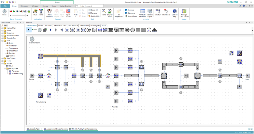
Figure 28: Final model of this chapter
