Chapter 3: Material Flow (I) – Object Inheritance, Frames and Model Structure
This chapter will introduce you to the modeling of material flow objects in Plant Simulation. After completing this chapter, you will be able to:
- Understand the modeling approach of Plant Simulation
- Know the difference between point-oriented and length-oriented modeling
- Create simulation models using material flow objects in Plant Simulation
- Run your simulation model
Modeling approach
One of the main features of Plant Simulation is the object-oriented modeling approach. By using this approach, you can define the properties of an object in a class, create multiple instances of this class, and make use of the inheritance between the class and its instances. You can imagine a class as a template, whereas instances are individual objects that are created using this template. When you define the attributes of a class, they will be passed on to all instances created from this class. This means that if you modify the value of an attribute in the class object, the change will also be applied in all instance objects derived from this class. This is more efficient and less error-prone than having to change the same property for each individual instance object every time.
However, you can also assign the value of an attribute individually for an instance object. This will overwrite the derived attribute in this instance object and deactivate the inheritance from the class object. The overwritten attribute in the instance object influences neither the attribute in the class object nor the attribute in other instances of the class. On the other hand, any change you make in the class object will not be applied anymore to the instance object, in which the inheritance is deactivated. Plant Simulation provides a toggle button to activate and deactivate the inheritances for each attribute. An active inheritance is shown using this icon ![]() , while inactive inheritance is shown using this icon
, while inactive inheritance is shown using this icon ![]() .
.
As mentioned in the previous chapter, we will refer to objects in the Class Library and the Toolbox as class objects. Objects that are inserted from the Class Library or the Toolbox into a Frame will be referred to as instance objects.
You can also define a new class object based on an existing class object in the Class Library. The Class Library provides the following methods to create a new class object from an existing class object:
- Right-click and select Duplicate
Duplicating a class object will create a new independent class object. All attributes of the existing class will be copied to the new class object, but the inheritance relations are severed. - Right-click and select Derive
Deriving a class object will create a new class object and keep the inheritance relation between the new and the existing class object. The new class object represents a subclass of the existing class object. Any changes made in the attribute of the class will be passed on to the subclass, as long as the inheritance for this attribute is still active.
To show all objects derived from a class object, right-click on the class object in the Class Library and select Show Inheritance. In the example shown in the figure below, you can see that the WorkerBeginner class was derived from the Worker class and the inheritance relations between them are still active. On the contrary, the WorkerAdvanced class was duplicated from the Worker class and therefore is not shown in the inheritance structure.
You can also see which properties are inherited in the subclass. In this example, the value for the attributes Priority and Capacity in the WorkerBeginner class are inherited from the Worker class, while the value for the attributes Efficiency and Speed are overwritten.

Figure 10: Class, subclass, and inheritances
By making use of object inheritances in Frame ![]() you can create a hierarchical structure of your simulation model. This means that you can model parts or area of your overall plant independently in different frames, make sure that these frames work by themselves, and then insert them into the main frame to build the entire plant.
you can create a hierarchical structure of your simulation model. This means that you can model parts or area of your overall plant independently in different frames, make sure that these frames work by themselves, and then insert them into the main frame to build the entire plant.
Interface ![]() connects the material flow into and out of the frame. You can only connect a frame to another object if the frame contains at least one interface. If an interface is connected to another object, Plant Simulation will automatically recognize based on the predecessor and successor relationship information whether the interface is an entrance or an exit of the corresponding frame.
connects the material flow into and out of the frame. You can only connect a frame to another object if the frame contains at least one interface. If an interface is connected to another object, Plant Simulation will automatically recognize based on the predecessor and successor relationship information whether the interface is an entrance or an exit of the corresponding frame.
Material flow objects within the same frame are connected by Connector ![]() . This connection is unidirectional and establishes the predecessor-successor relationship between material flow objects. Each predecessor and successor is numbered in the connector. You can see this relationship information if you hover with your mouse over a connector. Alternatively, you can always show them by right-clicking on the frame and selecting View Options → Show Predecessors or Show Successors.
. This connection is unidirectional and establishes the predecessor-successor relationship between material flow objects. Each predecessor and successor is numbered in the connector. You can see this relationship information if you hover with your mouse over a connector. Alternatively, you can always show them by right-clicking on the frame and selecting View Options → Show Predecessors or Show Successors.
Exercise: Create your model structure
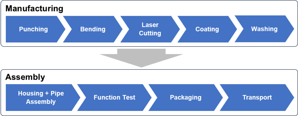
In this tutorial, we will model an example factory which produces radiators. The factory is divided into a manufacturing area and assembly area. In the manufacturing area, the raw material is processed through various manufacturing steps. In the assembly area, the processed part is assembled together with other purchased parts to form a finished product. The finished products are packaged and transported to shipment. An overview of the whole production process is shown in the figure below.
In this exercise, we will first create the structure of the factory using a top-down approach with frames. During the course of the tutorial, you will extend the model with further objects from the Class Library.

Figure 11: Overview of the production process
Step-by-Step
- Select Create New Model from the start page and select 2D at the dialog prompt.
- Plant Simulation will create a default frame under the Models folder in the Class Library. Select this frame and click F2 to rename it to “Plant”. This will be our main simulation frame.
- Right-click on the Models folder and select from the New → Folder from the context menu to create a new folder in the Class Library and nest it under the Models Rename the folder to “FacilityArea”.
- Right-click on the FacilityArea folder and select New → Frame from the context menu to create a new frame under this folder. Rename the frame to “Manufacturing”.
- Repeat the previous step and rename the frame to “Assembly”.
- Open the Manufacturing frame. Insert two Interfaces from the Toolbox into this frame. Rename the first one to “Entry” and the second one “Exit”. Try to adjust the position of the interfaces in the frame. Entry interface should be arranged on the left side of the frame and exit interface on the right side of the frame.
- Repeat the previous step in the Assembly frame.
- Open the Plant frame. Drag & drop the Manufacturing frame and the Assembly frame from the Class Library onto the Plant frame. This step will create an instance of the Manufacturing and Assembly frame each in the Plant frame.
- Connect these two frame instances in the Plant frame: Select the Connector from the Toolbox, left-click on the Manufacturing frame and select the Exit interface, left-click again on the Assembly frame and select the Entry interface.
- Save the model as Tutorial_Model_01.spp.
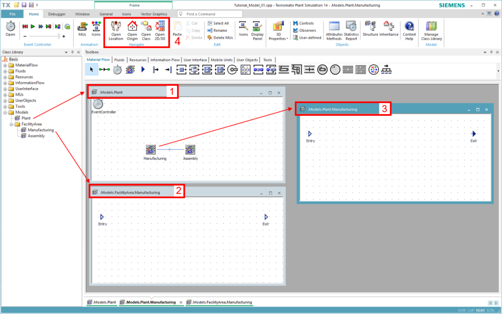
The figure below shows the state of the model after completing this exercise. You will notice that there are two Manufacturing frame objects, and correspondingly two Assembly frame objects. The Manufacturing frame in the Class Library (2) is the class object. It is referenced using the path .Models.FacilityArea.Manufacturing. The Manufacturing frame inside the Plant frame (3) is an instance of the class and is referenced using the path .Models.Plant.Manufacturing. You will also notice that the Exit interface in the instance is already connected, while the Exit interface in the class frame is not connected. When you are inside an instance object, you can always navigate to the class object by selecting Open Origin or Open Class from the Home ribbon tab (4).
The content of the Manufacturing instance (3) inside the Plant frame (1) is automatically inherited from the Manufacturing class (2). This way, you will be able to reuse the Manufacturing class in various other frames. If you try to add objects into the Manufacturing instance, you will get an error message as the structure of an instance frame is locked by default. You can click on Lock Structure on the Frame ribbon tab General to lock/unlock the frame structure.

Figure 12: Model structure
Modeling material flow – Mobile Units
The Mobile Units (MUs) are movable objects that move through the simulation model. They represent the flow of materials and requires other stationary material flow objects to process and transport them. There are three kinds of MUs:
- Entity
 represents parts that are produced, processed, and transported in the simulation model.
 - Container
 represents pallets, bins, boxes, etc. that can be used to load and transport one or multiple entities.
 - Transporter
 represents vehicles that can transport entities, containers, and other transporters. Transporter can move on its own on a length-oriented object, such as tracks or lines.
Source ![]() introduces MUs into the simulation. It creates the parts that will be processed in the production facility according to given parameters. The Source can produce MUs by defined time intervals, amount of MUs to be created, as well as based on a delivery table or trigger.
introduces MUs into the simulation. It creates the parts that will be processed in the production facility according to given parameters. The Source can produce MUs by defined time intervals, amount of MUs to be created, as well as based on a delivery table or trigger.
Drain ![]() destroys the MUs from the simulation. It typically represents the end of a production line. The statistics of the deleted MUs are collected by the Drain and can be used to calculate KPIs, e.g. the throughput of the production facility
destroys the MUs from the simulation. It typically represents the end of a production line. The statistics of the deleted MUs are collected by the Drain and can be used to calculate KPIs, e.g. the throughput of the production facility
Exercise: Mobile Units
In this exercise, we will extend the previous simulation model with a Source and a Drain. We will also define two new MU types in the simulation, one to represent the main part that is processed during manufacturing and one to represent the final assembled product.
Step-by-Step:
- Expand the MUs folder in the Class Library. Right-click on the Entity class and select Derive from the context menu.
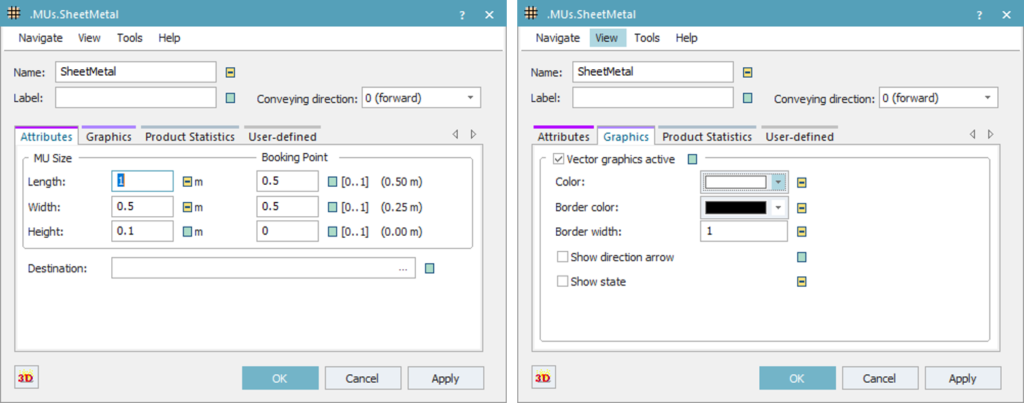
- Double-click on the derived Entity class and rename it to “SheetMetal”. Change the MU Size in the Attributes tab as shown in the figure below.
- Go to the Graphics tab. You will see that vector graphics are activated by default. In this case, Plant Simulation will show the animation of the parts with the correct size and correct distance to each other. If you wish to, you can change the color. Click on Apply or OK to apply the changes

Figure 13: Entity dialog properties
- Repeat the first step to derive another subclass of the Entity class.
- Double-click on the derived Entity class and rename it to “Radiator”. This will be our final assembled product. Change the MU Size in the Attributes tab to Length “1 m”, Width “0.5 m”, Height “1 m”, and set all Booking Point to “0.5”.
- Navigate to the Graphics tab and deactivate the vector graphics. In this case, Plant Simulation will show the default icons of the Entity during the animation.
- Right-click on the Radiator class and select Edit icons… from the context menu. There are two icons of the Entity by default, one for the operational state and one for the waiting state. Deactivate the Inheritance using the icon in the Edit ribbon tab. You can then change the size of the icon and paint the icon as you like, for example, like in the figure shown below. Now we can easily differentiate between the SheetMetal entity and Radiator entity during the simulation.Go to the Graphics tab. You will see that vector graphics are activated by default. In this case, Plant Simulation will show the animation of the parts with the correct size and correct distance to each other. If you wish to, you can change the color. Click on Apply or OK to apply the changes.
Figure 14: Edit icons
- Open the Plant frame. Insert one Source and one Drain from the Toolbox. Position the Source on the left side of the Manufacturing frame and the Drain on the right side of the Assembly frame.
- Select the Connector in the Toolbox and connect the objects as follows:
- Source to the Entry interface of the Manufacturing frame
- Exit interface of the Assembly frame to Drain
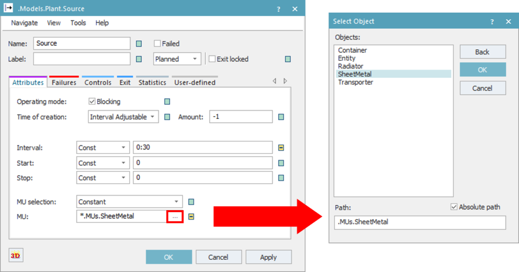
- Double-click on the Source instance. Change the attributes as shown in the figure below. Click on the button under next to MU under MU selection and choose Select Object. In the Select Object window, choose the SheetMetal entity and click OK. The Source will now produce one instance of the SheetMetal entity every 30 seconds.

Figure 15: Source dialog properties
Download:
The final state of the simulation model up to this exercise can be downloaded here Tutorial_Model_01
