Chapter 7: 3D Basics – Creating, Customizing and Running Models in the 3D Viewer
This chapter will give you a short introduction to the basics of 3D modeling in Plant Simulation. After completing this chapter, you will be able to:
- View and run simulation in 3D
- Understand 3D object properties
- Create 3D models using standard library elements
3D modeling in Plant Simulation
Plant Simulation provides a 3D Viewer to create and visualize simulation models in a three-dimensional space. When you create a new model, you can create your model directly in the 3D Viewer. Alternatively, you can also create your 2D simulation model first and activate the 3D visualization later on.
Exercise: 3D Model
In this exercise, we will run the simulation in the 3D Viewer and exchange a material flow object in 3D. Similar to previous exercises, it is highly recommended that you only make changes in the frames in the folder FacilityArea in the Class Library.
Step-by-Step:
- Open the Assembly frame in the folder FacilityArea. Click on the Open 2D/3D
 icon from the Home ribbon tab. If this is your first time creating the 3D model, Plant Simulation will ask if you want to create the 3D model with default graphics. Click on Yes. Plant Simulation will open the 3D viewer of this frame.
 - If you click on the icon Planning View
 in the View ribbon tab of the 3D ribbon group, Plant Simulation will change the view to the view from the top. This is especially helpful when you model length-oriented objects as you can edit them with more precise using the grids.
 - If you set the Worker to move freely within the area, Plant Simulation will use the material flow objects as obstacles for the workers. You can click on the icon Obstacles
 in the View ribbon tab to display these worker obstacles around the material flow objects, as shown in the figure below.
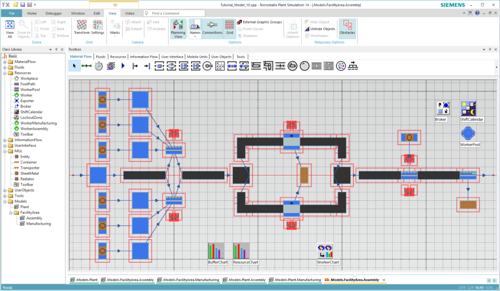
Figure 38: Planning view of the assembly frame with worker obstacles shown
- Now we want to replace the first Turnplate with a PickAndPlace This can be done in the 2D viewer as well as in the 3D viewer. Hold the Alt-key and drag & drop the PickAndPlace
 from the Toolbox onto the Turnplate in the frame to replace it. Click on Yes to copy all attributes in the appearing dialog window.
 - Deactivate the Planning View. You will see in the 3D viewer that a PickAndPlace robot is placed in place of the Turnplate. You can see this change in the 2D viewer as well.
- If you want to use another 3D model instead, right-click on the object and select Exchange Graphics… from the context menu. Choose the s3d graphics file that you want to use.
- Return to the Plant frame and open it in the 3D viewer as well. Run the simulation and open the Assembly frame of the Plant You will notice that the 3D model animation of the Radiator MUs hovers above the assembly station. This is because the size of the default 3D MU model differs from the MU size we defined in the previous step.
- Right-click on the Radiator entity in the MUs folder in your Class Library and select Edit 3D Properties… from the context menu. Navigate to the Graphics tab and click on the button Adjust Graphics to MU Size, as shown in the figure below. Click on Apply/OK.
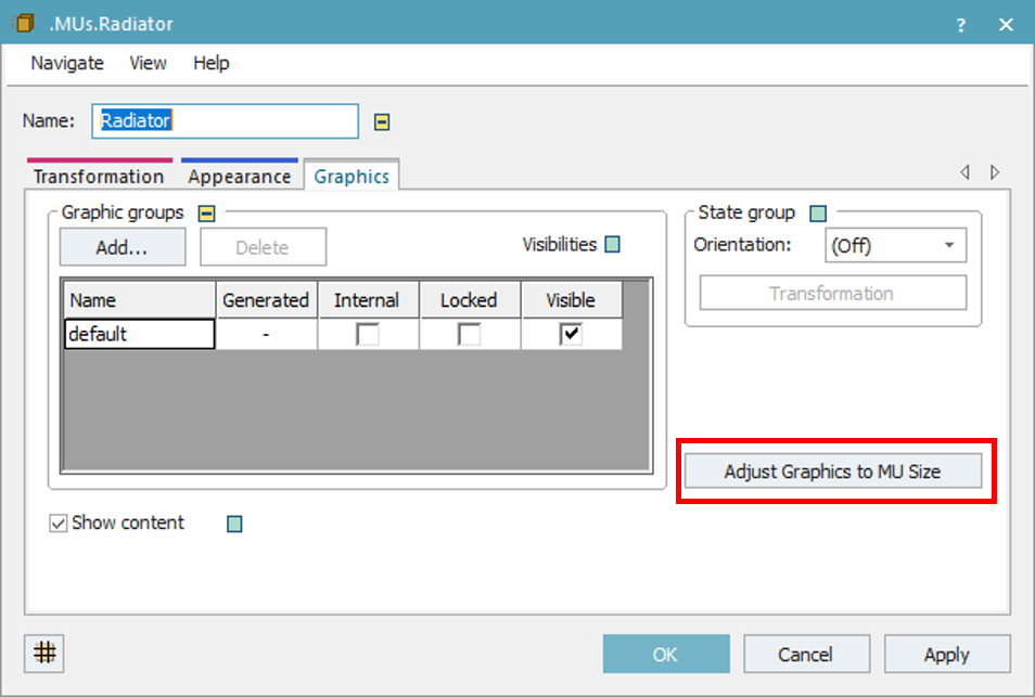
Figure 39: 3D properties of the MU
- Reset the simulation and run it again. Do you see any difference? Feel free to explore the 3D model more on your own
Download:
The final state of the simulation model up to this exercise can be downloaded here Tutorial_Model_09. Your simulation model should look similar to the figure below.
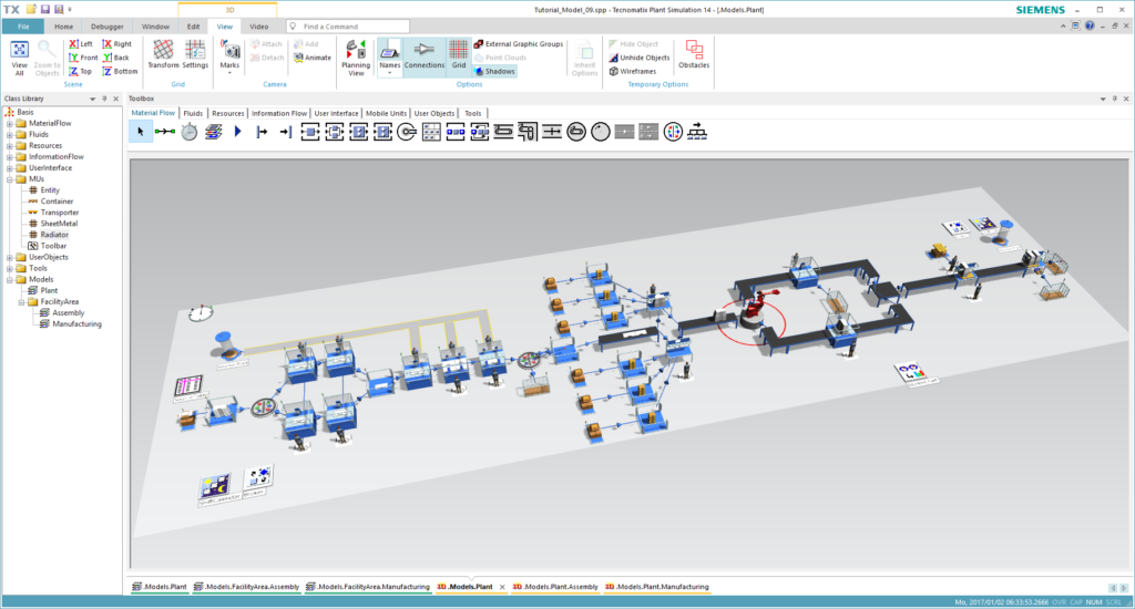
Figure 40: Final model of this chapter