Chapter 5: Modeling in Plant Simulation – Information Flow
This chapter will introduce you to the information flow objects and user-defined controls in Plant Simulation. After completing this chapter, you will be able to:
- Store information in table files and use them in your simulation
- Understand the Plant Simulation programming language SimTalk
- Extend your model with user-defined control functions
Table files
Plant Simulation provides multiple list and table objects to store information. They can be used to provide the simulation with input data which will be used during the simulation runs, as well as to record the simulation results.
TableFile ![]() is a list with multiple columns. Each individual cell in the table is indexed by its row and column number and can be accessed individually. Additionally, a table in a TableFile can contain another table.
is a list with multiple columns. Each individual cell in the table is indexed by its row and column number and can be accessed individually. Additionally, a table in a TableFile can contain another table.
CardFile ![]() , QueueFile
, QueueFile ![]() , and StackFile
, and StackFile ![]() are similar to the TableFile. However, they only consist of one column.
are similar to the TableFile. However, they only consist of one column.
Exercise: Set MU attribute from TableFile
In this exercise, we will extend the previous simulation with TableFile. We will define three different types of MUs in a TableFile and link the Source to the TableFile so that it will produce the MUs according to the attributes defined in the table. Similar to previous exercises, it is highly recommended that you only make changes in the frames in the folder FacilityArea in the Class Library.
Step-by-Step:
- Open the Plant Navigate to the Information Flow tab in the Toolbox. Insert a TableFile object from the Toolbox into the frame next to the Source and rename it to “SourceTable”.
- If you double-click on the SourceTable, you will see that each column currently has the same data type. You can show/hide the data type of the columns and rows using the icon Data Type
 from the List ribbon tab.
 - In the Plant frame, drag & drop the SourceTable onto the Source to link them.
- Double-click on the Source to open it. In the Attributes tab, you will see that instead of referring to the MUs directly, the Source now creates the MUs by referring to the SourceTable. Change the MU selection to “Percentage”.
- Double-click on the SourceTable to open it. You will notice that the structure of the table has changed. When a TableFile is linked to another object, the structure of the table and its data types will be automatically formatted according to the linked object.
- Drag & drop the SheetMetal entity from the folder MUs in the Class Library onto the rows below the first column. Edit the values of each row in the columns Portion, Number, and Name as shown in the figure below. The Source should produce in 50% of the time one RawPartA, 30% one RawPartB, and 20% one RawPartC.
- For each row of the Attributes column, set the value to “x”. This will automatically create a sub-table for each row where you can further specify the MU attributes. Set the Name of Attribute to “Type” and enter the corresponding attribute of the string type in the fourth column.
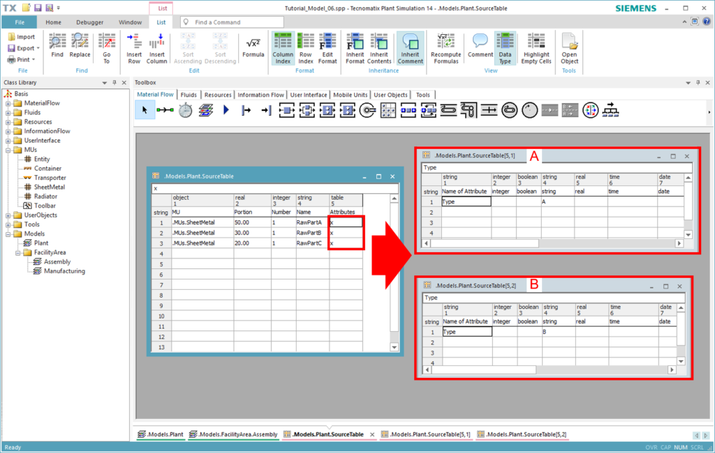
Figure 29: TableFile for defining MU attributes
- Open the Assembly frame in the folder FacilityArea in the Class Library. Double-click on the first Line which transports the parts from the inbound buffer to the assembly stations.
- Navigate to the Exit Change the strategy to “MU Attribute” and click Apply. You will be able to further specify the attribute type using a list. Set the Attribute type to “String” and click Apply.
- Click on the button Open List. We want to distribute parts with the attribute type “A” to the first succeeding station (Assembly1) and parts with the attribute type “B” or “C” to the second succeeding station (Assembly2). Enter the attribute “Type” in the table and set the values according to the figure below. Click on Apply/OK.
- Go back to the Plant frame and run the simulation. Did you notice any difference?
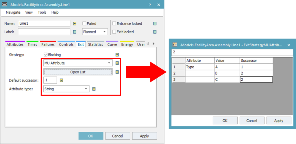
Figure 30: Exit strategy based on MU Attribute
Download:
The final state of the simulation model up to this exercise can be downloaded here Tutorial_Model_06.
Methods
Method ![]() represents a control object which is executed during the simulation run. You can program a specific action or define an individual behavior using Method. Method can also be built-in in material flow objects as an entrance or exit control. In this case, the action will be executed each time an MU enters or leaves the material flow object.
represents a control object which is executed during the simulation run. You can program a specific action or define an individual behavior using Method. Method can also be built-in in material flow objects as an entrance or exit control. In this case, the action will be executed each time an MU enters or leaves the material flow object.
There are also special types of methods which are called by the EventController. They are indicated with a special icon:
- Init Method
 is executed when you start the simulation model after resetting it.
 - EndSim Method
 is executed at the end of a simulation run.
 - Reset Method
 is executed when you click on the reset simulation button in the EventController.
Method contains source code written in the SimTalk programming language. The structure of a Method generally consists of parameters declaration, followed by the data type of the return value, local variables, and source code of the action itself.
You can write the code syntax in the SimTalk 1.0 syntax or in the newer SimTalk 2.0 syntax. One model can contain several methods with either SimTalk 1.0 or SimTalk 2.0, as they can run parallel. It is also possible to convert methods written in the old syntax to the new syntax. In SimTalk 2.0, the is-do-end constructor is obsolete. This results in a leaner and simpler code. The figure below shows an example of the notation in SimTalk 1.0 and SimTalk 2.0.
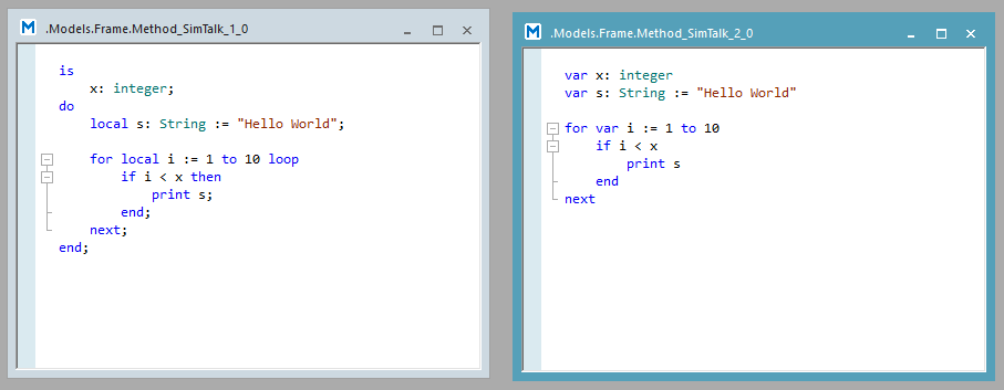
Figure 31: Notation of SimTalk 1.0 (left) vs. SimTalk 2.0 (right)
SimTalk consists of built-in methods and standard constructors, such as loops and conditional branching. To refer to an object in the simulation or query the path to an object, SimTalk provides the following anonymous identifiers:
- “@” refers to the MU that triggered the control. This may be the MU that entered the object or the MU that is ready to exit the object.
- “root” refers to the topmost (root) frame in the model frame hierarchy.
- “current” refers to the current frame in which the called Method object is located.
- “?” refers to the material flow object or the Method that triggered the control.
- “self” refers to the Method that is currently executed.
Exercise: Set MU attribute using Method
In this exercise, we will extend the previous simulation and model flow control based on MU attributes created using a Method. In the previous exercise, we modeled the QualityGate in the manufacturing area to sort the bad parts from the good parts and to only pass on the good parts. Instead of using the fixed percentage in the QualityGate, now we want to randomly assign the attribute whether an MU fulfills the quality requirement and make the decision based on the current attribute of the MU.
Similar to previous exercises, it is highly recommended that you only make changes in the frames in the folder FacilityArea in the Class Library.
Step-by-Step:
- Open the Manufacturing frame under the folder FacilityArea in the Class Library. Navigate to the Information Flow tab in the Toolbox. Insert a Method object from the Toolbox into the frame and rename it to “CheckPartOK”.
- Drag & drop the CheckPartOK method onto the Washing The icon of this Method should change to the icon of an exit control Method . Double-click on the Washing station and navigate to the Controls tab. Make sure that the CheckPartOK method is entered correctly in the Exit field.
- Double-click on the CheckPartOK method and enter the following SimTalk source code, as shown in the figure below. The Method will be executed each time an MU leaves the station.
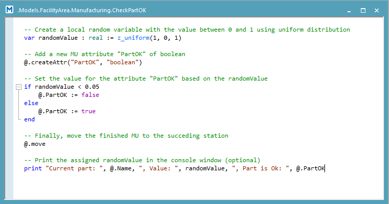
Figure 32: Source code of the exit control method
- Double-click on the QualityGate flow control object. Navigate to the Exit Strategy Change the strategy to “MU Attribute” and click Apply. Set the Attribute type to “Boolean” and click Apply.
- Click on the button Open List. We want to distribute parts of which the attribute “PartOK” is true to the succeeding assembly area and parts of which the attribute “PartOK” is false to the Rejects drain. Enter the values in the table as shown in the figure below. Click on Apply/OK.
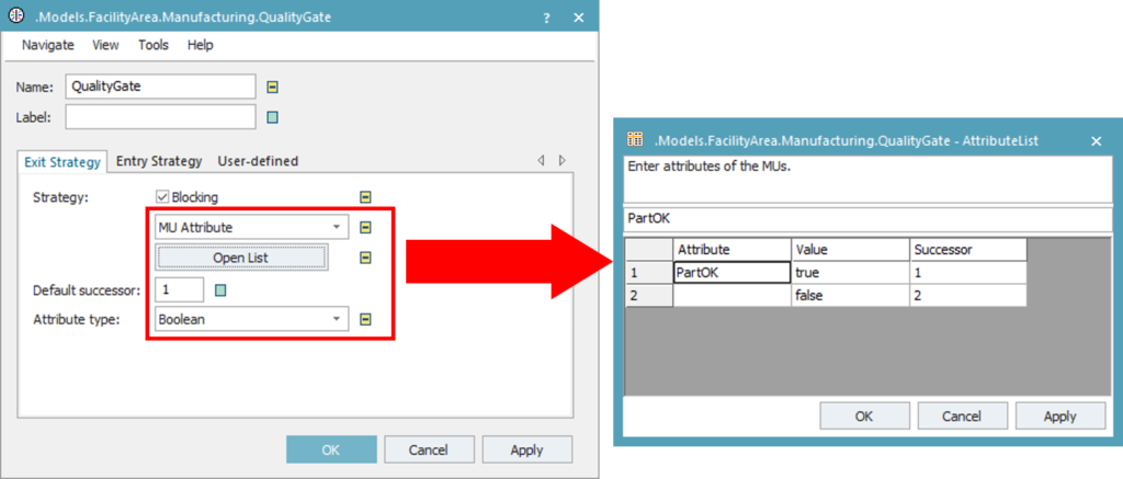
Figure 33: Exit strategy of the FlowControl
- Double-click on the QualityGate flow control object. Navigate to the Exit Strategy Change the strategy to “MU Attribute” and click Apply. Set the Attribute type to “Boolean” and click Apply.
- Open the Plant frame and run the simulation. Did you notice any difference to previous simulation runs?
- Try to experiment with different threshold values for the if-else-condition and see how it affects the simulation results. You can open the Console window to see which random values were generated by the simulation.
Download:
The final state of the simulation model up to this exercise can be downloaded here Tutorial_Model_07. Your simulation model should look similar to the figure below.
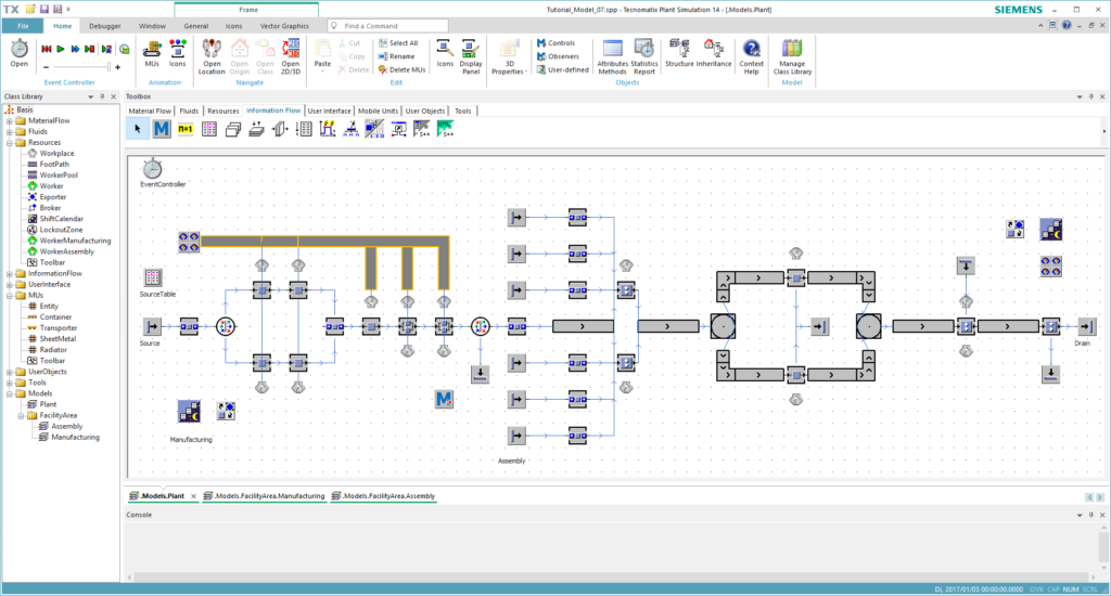
Figure 28: Final model of this chapter
